SCI论文(www.lunwensci.com)
摘要:压电驱动微操作提高柔性微操作器的实际定位性能。压电驱动微操作装置具有分辨率高、结构简单、体积小等优点, 在集 成电路制造和细胞操作领域得到了广泛的应用。在对压电驱动微操作装置的数据模型进行分析的基础上, 提出了一种基于 EUPI 逆 模型和 PID 相结合的控制策略 ( EIPID )。为了验证提出控制策略的性能, 基于 TMS320F2812 作为主控制芯片, 设计并测试了硬件 电路和软件程序。实验主要包含微动平台、 EUPI 模型、 EUPI 模型的仿真、 EUPI 逆模型、 EUPI 逆模型的仿真, 以及前馈PID 控制 器设计、开环实验、闭环实验等过程。实验结果表明, 基于 DSP 的 EIPID控制器比 EUPI 逆控制器具有更好的轨迹跟踪性能。 EUPI 逆控制器的平均静态跟踪误差比为 5.89%, 而 EIPID 控制器的平均静态跟踪误差比为 1.47%。因此, 该方法具有良好的控制效果。
Feedforward PID Control of the Piezoelectric Micromanipulator Using EUPI
Hysteresis Compensator
Zhu Mengdi1. Gao Jinhai2. Mi Lixia3. Liu Yifan4
( 1. School of Aeronautical Engineering, Binzhou University, Binzhou, Shandong 256600. China; 2. Shandong Aerospace Materials and DeviceEngineering Technology Research Center, Binzhou, Shandong 256600. China; 3.Binzhou Key Laboratory of Aerospace Optoelectronic Materials and Devices, Binzhou, Shandong 256600. China; 4. Finance Department of Binzhou Vocational College, Binzhou, Shandong 256603. China)
Abstract: Piezoelectric driven micromanipulation improves the actual positioning performance of flexiblemicromanipulator. Due to the advant- ages of high resolution, simple structure and small size, the piezoelectric driven micromanipulator has been widely used in the field of IC manufacturing and cell operation. However, it is difficult to deal with the nonlinear characteristics, such as hysteresis characteristic, and the traditional PID controller can not meet the needs of control accuracy and response speed of micromanipulator system . Based on the analysis of the data model of the piezoelectric driven micromanipulator, a new control strategy(EIPID) based on the combination of EUPI inverse model and PID is proposed. In order to verify the real-time performance of the EIPID algorithm, the DSP chip TMS320F2812 is selected as the main control chip. The hardware circuit and software program are disigned and tested . The experiment mainly includes fretting platform, EUPI model, EUPI model simulation, EUPI inverse model, EUPI inverse model simulation, feedforward PID controller design, open-loop experiment, closed- loop experiment and so on. The experimental result shows that the EIPID controller based on DSP has good trajectory tracking performance than EUPI inverse controller. The average static tracking error ratio of EUPI inverse controller is 5.89%, the average static tracking error ratio of EIPID controller is 1.47%. Thus, the method achieves a good control effect.
Key words: piezoelectric driven micromanipulator; positioning control; EIPID algorithm; DSP
0 引言
在过去数十年中, 微操作机器人成为微纳米技术的热点, 如 IC 制造、细胞操作和快速控制工程等领域[1-4] 。在这些应用中, 细胞微操作一直是研究的热点, 因为该技术是基因工程和药理学研究的关键手段。许多研究人员都致力于开发一种微操作机器人系统, 旨在以一种可靠、高通量和简单的方式操作细胞。然而,当前的系统并不能高效地完成相应的操作任务。因为微操作器有一个大的工作空间 (范围从微米到毫米),高分辨率、快速响应、适当的控制带宽和紧凑的尺寸[5]。本设计采用了压电驱 动的柔性结构,因为它具有输出纳米尺度运动的潜力。
压电驱动器是微操作器的核心驱动部件。压电陶瓷驱动器因其精度高、响应快、位移分辨率高、功耗低、抗干扰能力强等优点得到了广泛的应用[6]。微操作器的基本工作原理是在正常工作电压下, 压电材料的逆压电效应引起微操作器变形, 然后通过放大器和柔性支架使微定位平台移动[7]。然而, 压电陶瓷在某一时刻的位移不仅取决于当前值的电压, 而且还与压电陶瓷上一时刻负载电压有关, 这使得上升阶段和下降阶段之间的电压 位移曲线出现空心带, 即迟滞效应[8]。由于压电致动器 的迟滞非线性行为, 获得良好的数学模型是一项困难的 任务。因此, 这极大地影响了压电陶瓷驱动微操作平台 的定位精度和应用[9]。
迟滞效应在微定位平台的发展中一直是一个研究热 点, 因此国内外也出现了各种抑制迟滞效应的算法和模 型, 如文献[10- 11]模型利用广义 Prandtl-Ishlinskii 模型建 立迟滞回路, 并表明模型可以增强对对称迟滞特性的预 测。文献[12]利用前置逆 Preisach 模型对压电陶瓷致动器 的跟踪控制进行了预测,结果表明,与无迟滞补偿的控制 精度相比, 具有迟滞补偿的控制精度大大提高。文献[13] 基于 Bouc-Wen 模型补偿了压电材料中的强迟滞非线性, 该方法也适用于其他具有迟滞特性的系统。文献[14- 17] 采用改进迟滞模型来补偿压电执行器的滞特性。然而,当 满足精度要求时,算法程序就会变得更加复杂。但问题仍 然存在,如补偿器不能自动调整其参数以适应不同的操作 规模。为了提高求解效率, 本文基于前期研究 EUPI 迟滞 模型基础[18- 19], 分别研究并对比两种滞后补偿算法, 即 EUPI 逆补偿算法和前馈PID 补偿算法。最后, 在DSP 中实 现微动平台的补偿控制实验, 推动了该迟滞算法的应用。
1 微动平台
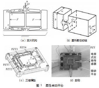
在本研究中, PZT 驱动的 2 自由度微动平台由两对放 大机构组成, 如图 1 ( a) 所示, 其工作原理为: 如果需 要平移运动, 可以根据实际要求在 PZT1、PZT2 或 PZT3 和 PZT4 施加电压, 通过放大机构将 PZT 输出位移转移到 平台使其进行 X 或 Y平移操作。此外, 柔性机构采用圆形 铰链 (图 1 (b) ), 比其他类型的柔性铰链[20] 具有更好的性能。其三维模型及实物如图 1 ( c )、(d) 所示, 关 于这一机构的设计可以在前期的研究[21-22] 中找到。
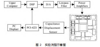
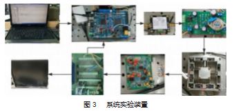
为了实现二维微动平台的线性控制, 该微操作器借 助于 DSP 和电容位移传感器实现了闭环控制。实验流程 如图 2 所示。系统实验装置如图 3 所示。考虑到大工作空 间的要求, 选用 4 个 PZT ( SZBS150/5×5/20. 苏州博实公 司) 驱动器。为了获得末端效应器在两个轴上的输出位 移, 选用两个高分辨率电容位移传感器 (MA-0.5. 北京 智达鼎盛公司), 本研究采用 DAQ 卡 (来自NI 公司的 PCI-6221)。为了提高计算速度, 采用了一种 DSP (来自 TI公司的TMS320F2812)。整个系统都安装在减振平台上。
2 EUPI 迟滞模型
2. 1 EUPI 模型
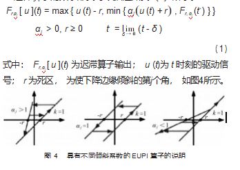
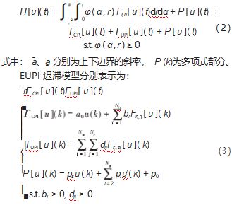
PZT 驱动器固有的迟滞特性给微定位系统引入强非 线性, 应抑制非线性, 以提高机构定位精度。近年来, 许多学者都致力于高精度迟滞模型的建立[10- 19], 并利用 迟滞模型来补偿其非线性。在这些模型中, EUPI 模型是 一种非常优越迟滞补偿算法, 由文献[18]提出, 其基本PI 迟滞算子的数学形式可以描述如式 (1) 所示。
复杂迟滞非线性效应可以分为对称滞后、不对称迟滞和无记忆多项式 3 个部分。模型表示如下: .
式中: ps 为线性增益系数的和 a0 ( >0) 的 CPI 部分和一阶 比例系数p1; bi 为 α 时 CPI 操作符的权重 i=1. 它用 d 分隔 ij; Nh 和 Np 分别为 CPI部分和多项式部分的算子数; 而 Nα 和 Nr 为在 EUPI 模型中对 α 和 r 的分割程度。
2.2 EUPI 模型的仿真
为了证明 EUPI 迟滞模型的建模性能, 使用从磁致 伸缩致动器中采集的实验数据进行了比较, 如图 5 所 示。由图可知, 使用 EUPI 建模方法显著提高了建模性 能。其非线性最大值约为 15.7%。显然, 该微机械手 很难满足电池注射和集成电路制造的精度要求。因此, 有必要采用滞后补偿控制来满足微机械手定位精度的 要求。
2.3 EUPI 逆模型
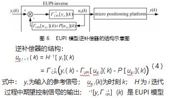
迟滞现象会降低设备微操作的控制精度, 甚至导致 系统不稳定, 因此对微操作的滞后补偿控制至关重要, 特别是在开环运行的条件下。为了有效地消除滞的影响, 最常用和最有效的方法是滞模型 。EUPI 模型的逆变量需 要以一种间接的方式来构建。由于 EUPI 模型可以分解为 CPI 、UPI 和多项式分量, 因此可以利用 CPI 分量的直接 解析逆。类似于在文献[23]中提出的方案。 EUPI 模型的 逆补偿结构如图 6 所示。
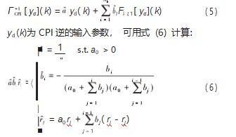
当 CPI 模型建立后, 可以通过式 (5) 得到唯一的表达式:
2.4 EUPI 逆模型的仿真
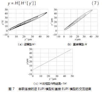
采用 EUPI 逆模型补偿微机械器的迟滞特性, 通过仿 真得到微平台的输入输出特性曲线。串联连接的逆 EUPI 模型和直接 EUPI 模型的交互结果如图 7 所示。整个过渡 函数如式 (7) 所示:
图 7 ( c ) 代表了整个系统输入 y*和输出 y 之间的关 系, 这提供了一个近乎理想的线性化, 从而补偿了微机
械手的迟滞非线性。然而, 系统线性化中的残差不确定 性是由于逆直接模型的输入输出离散化的结果, 这是面 向控制的模型实现必不可少的。因此, 本文提出了一种 基于 EUPI 逆模型的新型压电驱动微机械手控制器的前馈 PID 控制方法。
3 前馈 PID 控制器设计
迟滞逆补偿控制策略可以减少或消除迟滞特性的影 响。大多数的逆补偿控制器都是基于迟滞行为[24] 的逆模 型而设计的。消除剩余不确定性系统线性化结果的输入 输出离散化的逆和直接模型, 一个新颖的前馈 PID 控制 方案由 PID 控制器和 EUPI 滞后补偿器组成, 旨在提高实 际定位性能, 提出 2-DOF 微机械。为了验证迟滞补偿效 应, 对微机械手进行了闭环控制仿真。
3.1 前馈 PID 控制方案
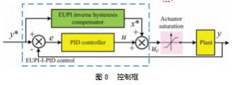
为了充分利用精确的迟滞模型, 设计了一种由 PID 和 EUPI 逆补偿器组成的复合 PID 控制器。复合 PID 控制 器通过修改积分进行调整, 积分包含一个逆方案的可调 参数, K 和一个积分器∫ 。K 既不应该太高也不应该过低, 如果过高会导致高数量的过调, 如果过低会会影响补偿 效应[19]。通过实验选择了 K 的最优值。控制框图如图 8 所示, 将 EUPI 逆迟滞补偿器 x* 的输出加到 PID 控制器 u 的输出信号中, 形成输入驱动电压信号 uc。
3.2 复合 PID 控制器的仿真分析
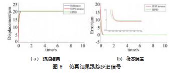
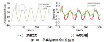
为了研究复合 PID 控制器的控制效果, 采用 EUPI 逆 控制器和复合 PID 控制器对微机械器的 EUPI 模型进行控 制, 以便进行比较。使用 MATLAB 进行模拟。分别应用 正弦信号 abs ( 15cos ( 0.1t) - 15) 和 20 振幅的步长信号 作为参考信号。通过齐格勒-Nichols 定理, 对 PID 和复合 PID 的控制参数进行调整, 发现最优值相同, 即比例为 0.01. 积分为 0.005. 导数为 0.对步进信号的仿真结果 如图 9 所示, 图 10 所示为对正弦信号的仿真结果。
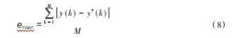
从图 9 和图 10 可以看出, 复合 PID 的控制效果优于 EUPI 逆控制器。为了进一步比较这两个控制器, 使用以 下功能引入了一个用于评价总体控制精度的准则:
式中: emean 为模型的平均误差比; y*(k) 和 y(k) 分别为 时间 k 时的期望位移和实际/模拟输出位移; M 为总采样 时间数。
在计算出跟踪正弦信号和步进信号时, 复合 PID 的 emean 值分别为 0. 15 μm 和 0.05 μm, 而 EUPI 逆控制器的值 分别为 0.25 μm 和 0. 12 μm, 这证明了复合 PID 控制器比 EUPI 逆补偿控制器具有更高的控制精度。
4 实验与分析
4.1 开环实验
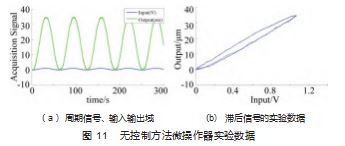
首先, 将一个具有恒定速率 (0. 1 rad/s) 的周期正弦 信号应用于具有 PZT 的微操纵器。通过使用固定采样步 长 (0.01 s) 获取输入和输出位移, 相关结果如图 11 所 示。可以看出, 该系统的迟滞效应约为 15.3%。此外, 迟滞曲线的平滑性并不令人满意, 这主要是由迟滞非线 性、传感器噪声、装配误差等干扰引起的。
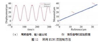
然后, 利用 DSP 进行了 EUPI 逆控制实验, 验证了该 控制器和所开发的微操作器的有效性。输入信号为正弦 信号, 其振幅值设置为 1.1. ω 设置为 0. 1 rad/s。在 EUPI 逆控制方法过程下, 测量传感器 300 s 的输出电压, 曲线 如图 12 所示。通过图 12. 经过 EUPI 逆补偿控制后, 传 感器的输出比无控制的开环得到更好的补偿。但 EUPI 逆 模式是一种开环控制方法, 传感器的输出在系统运行过 程中存在外部扰动, 升高点如图 12 (b) 红色箭头所示。 因此, 在强干扰中会出现信号突变, 不可避免地会影响 微操纵器的控制精度。
4.2 闭环实验
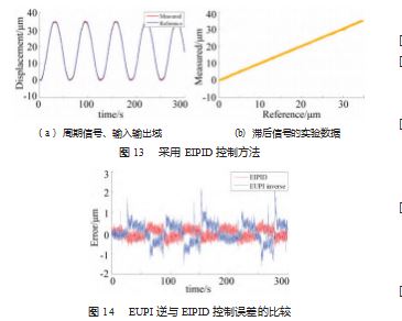
为了抑制 EUPI 逆控制的干扰信号, 采用了基于 EU⁃ PI 逆控制与 PID 相结合的控制策略 (EIPID)。输入信号 为正弦信号, 其振幅设置为 34.5. ω 设置为 0. 1 rad/s。通 过调整 PID 参数, 通过测量 300 s 的输出电压, 曲线如图 13 所示。由图可知, 经过 EIPID 补偿控制后, 传感器的 输出比开环得到更好的补偿。此外, 该控制模式为闭环 控制, 对外部干扰具有较好的误差补偿。通过计算, 定 位误差约为 1.47%, 小于 5.89%, 如图 14 所示, 可以有 效地抑制微机械手的迟滞非线性。
5 结束语
为了提高柔性微操作器的实际定位性能, 本文提出 了一种新型的 EIPID 控制器。考虑到 PZT 执行器固有的 滞非线性效应, 利用 EUPI 理论进行了滞建模。在此基础 上, 利用所建立的迟滞模型, 提出了一种新的前馈 PID 闭环控制器, 并通过仿真试验验证了其有效性。最后, 进行了一系列的轨迹跟踪实验, 验证了其实际的定位性 能。实验结果一致表明, 所开发的微机械手在实际生物 化学操作中取得了令人满意的性能。
参考文献:
[1] Floyd S, Pawashe C, Sitti M. Two-dimensional contact and non ⁃ contact micromanipulation in liquid using an untethered mobile magnetic microrobot[J]. IEEE Transactions on Robotics, 2009. 25 (6):1332- 1342.
[2] Agnus J, Chaillet N, Clévy C, et al. Robotic microassembly and micromanipulation at FEMTO-ST[J]. Journal of Micro-Bio Ro ⁃ botics, 2013.8(2):91- 106.
[3] Tang Hui, Li Yangmin. Feed forward nonlinear PID control of a novel micro manipulator using Preisach hysteresis compensator [J]. Robotics and Computer-Integrated Manufacturing, 2015(34): 124- 132.
[4] Elgammal A T, Fanni M, Lashin M, et al. Dynamic modeling and robust motion control of a 2D compliant pantograph for microma⁃nipulation[C]//Control, Automation and Robotics (ICCAR), 2016 2nd International Conference on. IEEE, 2016: 159- 164.
[5] Lu Z, Moraes C, Zhao Y, et al. A micromanipulation system for single cell deposition[C]//Robotics and Automation (ICRA), 2010 IEEE International Conference, 2010: 494-499.
[6] Janaideh M A, Rakotondrabe M, Aljanaideh O. Further Results on Hysteresis Compensation of Smart Micropositioning Systems With the Inverse Prandtl-Ishlinskii Compensator[J]. IEEE Trans ⁃actions on Control Systems Technology, 2015. 24(2):1- 1.
[7] Jaffe B. Piezoelectric ceramics[M]. Elsevier, 2012.
[8] Morozov M I, Einarsrud M A, Tolchard J R, et al. Hysteresis in piezoelectric and ferroelectric materials[J]. Journal of Applied Physics, 2015. 99(16):557- 1344.
[9] Qin Y, Tian Y, Zhang D, et al. A novel direct inverse modeling approach for hysteresis compensation of piezoelectric actuator in feedforward applications[J]. IEEE/ASME Transactions on Mecha ⁃tronics, 2013. 18(3): 981-989.
[10] Al Janaideh M, Rakheja S, Su C Y. A generalized Prandtl-Ish ⁃ linskii model for characterizing the hysteresis and saturation nonlinearities of smart actuators[J]. Smart Materials and Struc ⁃ tures, 2009. 18(4): 045001.
[11] Al Janaideh M, Rakheja S, Su C Y. An analytical generalized Prandtl – Ishlinskii model inversion for hysteresis compensation in micropositioning control[J]. IEEE/ASME Transactions on Me ⁃chatronics, 2011. 16(4): 734-744.
[12] Song G, Zhao J, Zhou X. Tracking control of a piezoceramic ac ⁃ tuator with hysteresis compensation using inverse Preisach mod ⁃ el[J]. IEEE/ASME Trans. Mechatron, 2005(10):198-209.
[13] Rakotondrabe M. Bouc-Wen modeling and inverse multiplica⁃ tive structure to compensate hysteresis nonlinearity in piezoelec ⁃ tric actuators[J]. IEEE Transactions on Automation Science and Engineering, 2011. 8(2): 428-431.
[14] Xiao S, Li Y. Modeling and high dynamic compensating the rate-dependent hysteresis of piezoelectric actuators via a novel modified inverse Preisach model[J]. IEEE Transactions on Con ⁃trol Systems Technology, 2013. 21(5): 1549- 1557.
[15] Habineza D, Rakotondrabe M, Gorrec Y L. Bouc – Wen Model⁃ing and Feedforward Control of Multivariable Hysteresis in Piezoelectric Systems: Application to a 3-DoF Piezotube Scan ⁃ ner[J]. IEEE Transactions on Control Systems Technology,2015. 23(5):1797- 1806.
[16] Gu G Y, Yang M J, Zhu L M. Real-time inverse hysteresis com ⁃ pensation of piezoelectric actuators with a modified Prandtl-Ish ⁃ linskii model[J]. Review of Scientific Instruments, 2012. 83(6):065106.
[17] Wang G, Chen G, Zhou H, et al. Modeling and tracking control for piezoelectric actuator based on a new asymmetric hysteresis model[J]. IEEE/CAA Journal of Automatica Sinica, 2016.
[18] Sun Z, Song B, Xi N, et al. Compensating asymmetric hysteresis for nanorobot motion control[C]//Robotics and Automation (ICRA), 2015 IEEE International Conference on. IEEE, 2015: 3501-3506.
[19] Xiang C, Yang H, Sun Z, et al. The design, hysteresis modeling and control of a novel SMA-fishing-line actuator[J]. Smart Ma ⁃ terials and Structures, 2017. 26(3): 037004.
[20] Tang H, Li Y. Design, analysis and test of a novel 2-DOFnanopositioning system driven by dual-mode[J]. IEEE/Trans. Robot,2013:29(3):650-662.
[21] 郝丽娜, 曹瑞珉 . 一种具有双位移放大的大行程快速响应 X- Y 微动工作台:CN201410165010.0[P]. 2017-05-03.
[22]曹瑞珉,郝丽娜, 高金海 . 一种大工作空间密度的压电微动二 维工作台设计[J]. 中国机械工程,2017.28(9):1016- 1020.
[23] Z Li, Y Feng, T Chai. Modeling and compensation of asymmet⁃ ric hysteresis nonlinearity for magnetostrictive actuators with an asymmetric shifted prandtlishlinskii model[C]// American Con⁃ trol Conference (ACC), 2012:1658- 1663.
[24] Kuhnen, Klaus, H Janocha. Inverse feedforward controller for complex hysteretic nonlinearities in smart-material systems[J]. Control & Intelligent Systems, 2001.29(3):74-83.
关注SCI论文创作发表,寻求SCI论文修改润色、SCI论文代发表等服务支撑,请锁定SCI论文网!
文章出自SCI论文网转载请注明出处:https://www.lunwensci.com/ligonglunwen/64888.html